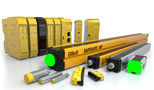
JANUS – Status display
Emitter – JANUS ML / MT
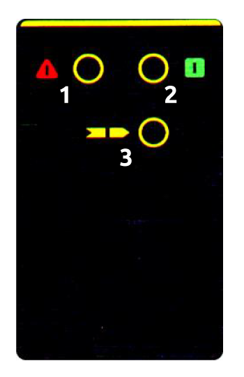
| 1 Red LED | 2 Green LED | 3 Yellow LED | Meaning |
| ⊗ | ⊗ | ⊗ | System power-on – Initial TEST for 5 seconds |
| ⊗ | ⊗ | ⊗ | Test conditon |
| ⊗ | ⊗ | ⊗ | GUARD condition |
| ⊗ | ⊗ | ⊗ | FAIL condition. See next “fail condition table” |
Fail condition
| 1 Red LED | 2 Green LED | 3 Yellow LED | Meaning |
| ⊗ Blinking | ⊗ | ⊗ | Internal fault |
| ⊗ Blinking | ⊗ | ⊗ Blinking | |
| ⊗ Blinking | ⊗ Blinking | ⊗ |
Emitter – JANUS MI / J / J LR
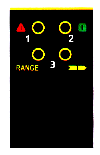
| 1 Red LED | 2 Green LED | 3 Yellow LED | 4 RANGE | Meaning |
| ⊗ | ⊗ | ⊗ | ⊗ | System power-on – Initial TEST for 5 seconds |
| ⊗ | ⊗ | ⊗ | ⊗ | Test conditon |
| ⊗ | ⊗ | ⊗ | ⊗ | GUARD condition |
| ⊗ | ⊗ | ⊗ | ⊗ | High range selected |
| ⊗ | ⊗ | ⊗ | ⊗ | FAIL condition. See next “fail condition table” |
Fail condition
| 1 Red LED | 2 Green LED | 3 Yellow LED |
4 RANGE |
Meaning |
| ⊗ Blinking | ⊗ | ⊗ | ⊗ | Internal fault |
| ⊗ Blinking | ⊗ | ⊗ Blinking | ⊗ | |
| ⊗ Blinking | ⊗ Blinking | ⊗ | ⊗ | |
| ⊗ Blinking | ⊗ | ⊗ | ⊗ Blinking | Correct the range selection on the Emitter Unit |
Receiver – JANUS MI / ML / MT and ACTIVE ELEMENT JANUS MI TRX / ML TRX / MT TRX
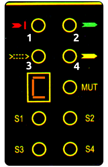
| 1 Red LED | 2 Green LED | 3 Orange LED | 4 Clear/Override LED | S1 LED | S2 LED | S3 LED | S4 LED | MUT LED | C Display | Meaning |
| ⊗ | ⊗ | ⊗ | ⊗ | ⊗ | ⊗ | ⊗ | ⊗ | ⊗ | 8 | System power-on – Initial TEST for 5 seconds |
In the next 10 seconds, the display and the leds will show the configuration selected
| LED | Status | Meaning |
| S1 | ⊗ | Enabling of timeout 30 s. |
| S1 | ⊗ | Enabling of timeout 90 min. |
| S2 | ⊗ | With 4 sensors, enabling of sequential Muting |
| S2 | ⊗ | With 4 sensors, enabling of concurrent operation mode |
| S3 | ⊗ | Manual restart functioning mode enabled |
| S3 | ⊗ | Automatic restart functioning mode enabled |
| S4 | ⊗ | External relays feedback control enabled |
| S4 | ⊗ | External relays feedback control disabled |
| MUT | ⊗ | Muting configuration with 4 sensors |
| MUT | ⊗ | Muting configuration with 2 sensors |
| 1 Red LED | ⊗ | OSSD outputs set to OFF |
| 4 Clear/Override | ⊗ | Automatic override with pulse command |
| 4 Clear/Override | ⊗ | Manual overrun action with hold to run |
| Display | C | Configuration |
During the normal functioning
| LED | Status | Meaning |
| S1 | ⊗ | Interruption Sensor 1 |
| S1 | ⊗ | Sensor 1 clear |
| S2 | ⊗ | Interruption Sensor 2 |
| S2 | ⊗ | Sensor 2 clear |
| S3 | ⊗ | Interruption Sensor 3 |
| S3 | ⊗ | Sensor 3 clear |
| S4 | ⊗ | Interruption Sensor 4 |
| S4 | ⊗ | Sensor 4 clear |
| MUT | ⊗ | Muting active |
| MUT | ⊗ | Light curtain active – GUARD condition |
| 1 Red LED | ⊗ | OSSD outputs set to OFF |
| 2 Green LED | ⊗ | GUARD condition |
| 3 Orange LED | ⊗ | Weak signal |
| 4 Clear/Override | ⊗ | Light curtain in override, OSSD outputs set ON. “o” letter appears on the display and at the same time the external Muting/Override lamp blinks. |
| 4 Clear/Override | ⊗ Blinking | Override request |
| Display | – | During normal functioning |
| F – Code | Fault detected. Displayed alternatively to the error code. See next “Fail condition Table” |
Fail condition
Configuration errors
- C: Incorrect configuration of the system (the flashing led together with the C indicates the incorrect type of configuration). See Technical manual
- L: Muting light not present or fault
- U: Incorrect “SYSTEM STATUS” or overload signal connection
- E: External contact enabling/disabling signal missing or contactors feedback missing
- II: Unstable Muting sensors signals or Barrier configured for 2 sensors but found 3 or 4 sensors (the corrispondent led flashes)
Faults
- 3: Internal error
- 4: Internal error
- 5: Internal error on the OSSD outputs (or incorrect connection of these)
- 6: Short–circuit between the OSSD outputs
- A: Internal error
- 0: Overload of the OSSD outputs
- 1: Interfering Emitter detected (The code remains visibile for at least 30s)
- t: Override with pulse command expired
Receiver – JANUS J / J TRX / J TRX
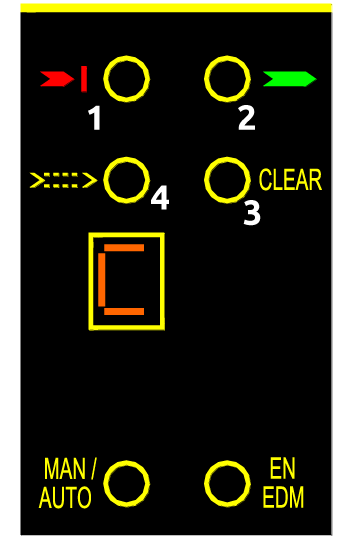
| 1 Red LED | 2 Green LED | 3 Orange LED | 4 Clear/Override LED | MAN/AUTO LED | EN EDM LED | C Display | Meaning |
| ⊗ | ⊗ | ⊗ | ⊗ | ⊗ | ⊗ | 8 | System power-on – Initial TEST for 5 seconds |
In the next 10 seconds, the display and the leds will show the configuration selected
| LED | Status | Meaning |
| MAN/AUTO LED | ⊗ | Manual restart functioning mode enabled |
| MAN/AUTO LED | ⊗ | Automatic restart functioning mode enabled |
| EN EDM LED | ⊗ | External relays feedback control enabled |
| EN EDM LED | ⊗ | External relays feedback control disabled |
| 1 Red LED | ⊗ | OSSD outputs set to OFF |
| Display | C | Configuration |
During the normal functioning
|
LED |
Status | Meaning |
| 1 Red LED | ⊗ | OSSD outputs set to OFF |
| 2 Green LED | ⊗ | GUARD condition |
| 3 Orange LED | ⊗ | Weak signal |
| 4 Yellow LED | ⊗ | Light curtain clear, OSSD outputs set OFF (the receiver is waiting for a Restart signal) |
| Display | – | Normal functioning |
| F – CODE | Fault detected. Displayed alternatively to the error code. See next “Fail condition Table” |
Fail condition
Configuration errors
- C: Incorrect configuration of the system (the flashing led together with the C indicates the incorrect type of configuration). See Technical manual
- E: External contact enabling/disabling signal missing or contactors feedback missing
Faults
- 0: Overload of the OSSD outputs
- 1: Interfering Emitter detected (The code remains visibile for at least 30s)
- 2: Outputs OSSD incorrectly connected to +24VDC
- 3: Internal error
- 4: Internal error
- 5: Internal error on the OSSD outputs (or incorrect connection of these)
- 6: Short circuit between the outputs OSSD
- A: Internal error