Mosaic analog safety modules (MA2 – MA4) and analog sensors
Often, in machines and industrial plants, there are process that require safety functions capable of reaching PL or SIL levels. For example, the EN528 standard for stacker cranes requires a weight control with a performance level
PL r = d. To meet this need, the MA2 and MA4 modules, capable of carrying out a safe evaluation of analog quantities, have been added to the Mosaic range.
The MA2 and MA4 modules are certified according to the 2006/42/EC Machinery Directive. They also comply with the standards of the EN IEC 61508 series, so they can also be used in process plants, for SIS systems and SIF functions.
The MA2 and MA4 modules can manage 2 or 4 analog input channels. These inputs can be used individualli or in pairs.
- When the inputs are used individually, depending on the sensors connected, the system can reach a safety level up to SIL 2 / PL d.
- When the inputs are used in pairs, depending on the sensors connected, the system can reach a safety level
SIL 3 / PL e.
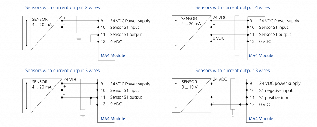
Each analog input is fully isolated up to 500 VDC. MA2 and MA4 can be configured to be connected to 1 or 2 sensors having a current output (0 ÷ 20 mA, 4 ÷ 20 mA) or having a voltage output (0 ÷ 10 V). In addition, various connection configurations are possible.

There are also sensors capable of measuring both positive and negative values. Mosaic analog modules can also accept negative values from the sensors (for example a flow in both directions, the pressure can also be empty, etc.).
In this case the output signal may have, for example:
- A minimum full scale that refers to a negative value (4 mA)
- A maximum full scale that refers to a positive value (20 mA)
- The zero value will be placed in the centre of the scale (12 mA)
MA2, MA4 modules used with safety analog sensors
On the market are available analog sensors already certified SIL (Typically IEC 61508). These standard is mainly used in the world of process industry and less known in the world of machines and industrial automation where EN ISO 13849-1 /2 and EN 62061 are used. For example:
- Temperature sensors
- Flow sensors
- Pressure sensors
- Lower explosive limit (LEL) sensors for Atex zones
- Weight sensors
- Flame sensors
- Transducers of physical quantities in current signals from 4 to 20 mA always with SIL certifications.
The use of these sensors already SIL rated makes it easier the calculation of the overall safety integrity of the safety function.
Simplifying as much as possible, let’s look at example.
Safety level according to IEC 61508
| Sensors | MA2, MA4 | Application Safety level |
| 1 sensor SIL 3 | SIL 3 | SIL 3 |
| 2 sensors SIL 2 | SIL 3 | SIL 3 |
| 2 sensors SIL 1 | SIL 3 | SIL 2 |
| 1 sensor SIL 2 | SIL 3 | SIL 2 |
| 1 sensor SIL 1 | SIL 3 | SIL 1 |
MA2, MA4 modules used with non-safety analog sensors
There are non-safety analog sensors on the market. Using the Mosaic MA2 and MA4 analog modules, these sensors can also be used for safety functions according to EN ISO 13849. We consider EN ISO 13849-1 as it is the standard that is most frequently used in the field of machines.
The characteristics of the MA2 MA4 modules allow to connect 2 measurement sensors, to put them in relation to each other, creating redundancy and cross monitoring to increase the total safety level of the system. In this way it is possible to verify the measurement and obtain a security level higher than that obtainable using a single sensor.
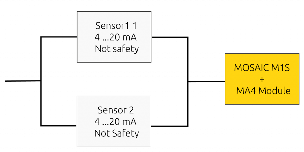
Automation sensors can be used, e.g. without the PL / SIL safety level declared by the manufacturer and in any case achieve a very high safety level, up to SIL 3 / PL e, satisfying all the conditions required by the standards. Beside a logical representation of the system.
An example will be presented below where the most important aspects of the assessments to be performed will be analysed and the procedures that must be performed to ensure that, with the Mosaic system, the required level of safety is achieved.
The example shows: Non-safety sensors (without PL / SIL declared by the manufacturer) 4-20 mA and Mosaic M1S with MA4 module.

We will then analyse which is the achievable PL and under what conditions.
This architecture represents a pair of analog sensors that measure the same physical quantity.
It is necessary to verify that:
- The safety function SF, generates a stop signal (not represented here) when a certain threshold value is exceeded
- The behaviour in case of failure has been well identified. With safety systems that measure analog quantities, the evaluation of the behaviour in the event of a fault is more complex. Behaviour must be evaluated and the decision is often not unique. In general, in case of a component failure, The system must consider the signal coming from the faulty component as if it had exceeded the threshold beyond which the machine must be stopped (safety-oriented fault).
- The safety related software has been created according to EN ISO13849-1 §4.6
- Systematic failures are checked and excluded (EN ISO13849-1 Annex G)
- The ability to perform the safety function under the expected environmental conditions is verified
The architecture with 2 sensors indicates a category 3 or 4 due to the presence of redundancy. We will check which conditions must be met to obtain Category 4 or Category 3.
Reference should be made to table 10 of ISO 13849-1, which deals with making a first classification:
Reference should be made to table 10 of ISO 13849-1, which deals with making a first classification:
| Category | Summary of requirements | System Behaviour | Principles used to achieve safety | MTTFD of each channel | Diagnostic coverage (DCavg) |
Common cause failure (CCF) |
| B | Design according to the basic safety principles | The occurrence of a fault can lead to the loos of safety function | Mainly characterized by selection of components. | Low | None | Not relevant |
| 1 | Requirement of B + well tried components and well tried safety principles shall be used | The occurrence of a fault can lead to the loos of safety function but the probability of occurrence is lower than for category B | Mainly characterized by selection of components. | High | None | Not relevant |
| 2 | Requirement of B + Safety function test at «appropriate» intervals | The occurrence of a fault can lead to the loos of safety function between one test and another. The test recognizes the loss of the safety function | Architecture | Low | Low -Medium | Check |
| 3 | Requirement of B + a single fault must not lead to the loss of the safety condition and if possible, the single fault must be identified | A single fault must not lead to the loss of the safety condition. Some faults need to be identified. The accumulation of faults can lead to the loss of the safe condition | Architecture | Low | Low -Medium | Check |
| 4 | Requirement of B + a single fault must not lead to the loss of the safety condition | The single fault must be identified before the need for intervention and in any case the accumulation of faults must not lead to the loss of the safety condition A single fault must not lead to the loss of the safety condition. The identification of accumulated faults (high DCavg) reduces the probability of loss of the safe condition | Architecture | High | High and includes the accumulation of faults | Check |
Following the instructions in the table, we need to:
- Compliance with relevant standards for resistance to expected influences (Check sensor manufacturer’s datasheet).
- Use of basic safety principles.
- Use of well-tried safety principles.
- Single fault tolerance and reasonably foreseeable fault detection
NOTE: Sensors Sensors with 0-5V voltage outputs.
These sensors can be connected to modules configured for voltage input by selecting in the MSD Software a full scale value two times higher. Example: if full scale is 100 kg at 5V, 200 kg must be selected.
In this case, 1 bit of resolution will be lost out of the 16 available.


 Italiano
 English
 Deutsch
 Português
 简体中文
简体中文 Français
 한국어
한국어

